
H5CX-ASD-N AC/DC 24
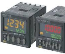
Type: H5CX-ASD-N AC/DC 24
Rated supply voltage
24 VAC 50/60 Hz
12 to 24 VDC 20% max.
Operating voltage range
85% to 110% of rated supply voltage (90% to 110% at 12 to24 VDC)
Power consumption
5.1VA (at 24 VAC)
2.4W (at 24 VDC)
Time ranges(Number of ranges)
10
Time ranges
0.001 s to 9.999 s / 0.01 s to 99.99 s / 0.1 s to 999.9 s / 1 s to 9999 s / 0.1 min to 999.9 min / 1 min to 9999 min / 0.1 h to 999.9 h / 1 h to 9999 h
1sec~99min59sec
Select method
Dip switch or Operation Key
Input signals
Signal, Gate, Reset
Input method
No-voltage/Voltage input (selectable)
No-voltage input(Solid state input)
ON impedance: 1 kΩ max.
Leakage current: Approx. 12 mA
ON residual voltage: 3 V max.
OFF impedance: 100 kΩ min.
(The DC voltage must be 30 VDC max.)
No-voltage input(Contact input)
Use contact which can adequately switch 5 mA at 10 V
(The DC voltage must be 30 VDC max.)
No-voltage input(Applicable two-wire sensor)
Leakage current: 1.5 mA max.
Switching capacity: 5 mA min.
Residual voltage3.0 VDC max.
Operating voltage: 10 VDC
Voltage input
High level: 4.5 to 30 VDC
Low level: 0 to 2 VDC
Input resistance: 4.7 kΩ
(The DC voltage must be 30 VDC max.)
Output modes
A (Signal ON delay1)
A-1 (Signal ON delay2)
A-2 (Power ON delay1)
A-3 (Power ON delay2)
b (Repeat cycle1)
b-1 (Repeat cycle2)
d (Signal OFF delay)
E (Interval)
F (Cumulative)
Z (ON/OFF-duty adjustable flicker)
S (Stopwatch)
toff (Flicker OFF start1)
ton (Flicker ON start1)
toff-1 (Flicker OFF start2)
ton-1 (Flicker ON start2)
Control output (Solid state output)
Transistor output (NPN open collector)
Switching capacities: 100 mA max. 30 VDC max.
Residual voltage: 1.5 V(Ability approx.1 V)
Leakage current: 0.1 mA
One-shot output time
0.01 to 99.99 s
Reset system
Power reset (depending on output mode) / Automatic reset (depending on output mode) / External reset / Manual reset
Power reset
Minimum power-opening time: 0.5 s (except for A-3, b-1, F, ton-1 and toff-1 mode)
Timer mode
Elapsed time (UP) and remaining time (DOWN) (selectable)
Display method
7-segment negative transmissive LCD
Digit
4 digit
Character height
Present value: 12 mm (Red, green or orange programmable)
Set value: 6 mm (Green)
Key protect method
Key protect Switch
Memory backup method
EEP-ROM
Number of rewite: 100,000 operations min. / Service life: 10 years min.
Ambient temperature
Operating: -10 to 55 ℃ When mount timer side by side: -10 to 50 ℃
Storag: -25 to 70 ℃
Ambient humidity
Operating: 25 to 85%RH
Total accuracy
Accuracy of operating time and setting error (including temperature and voltage influences)
Power-ON start: ±0.01% ±50 ms max.
The values are based on the set value.
Accuracy of operating time and setting error (including temperature and voltage influences)
Signal start: ±0.005% ±3 ms max. (The value is applied for a minimum pulse width of 1 ms.)
The values are based on the set value.
Insulation resistance
100 MΩ min. (at 500 VDC)
Between current carrying terminals and exposed non-current carrying metal parts / Between non-continuous contacts
Dielectric strength
Between current carrying metal parts and non-current carrying metal parts: 2000
between control output and power/input circuit: 1000
Between non-continuous contacts: 1000
Impulse withstand voltage
Between power terminals: 1.0 kV
Between current carrying terminals and exposed non-current carrying metal parts: 1.5 kV
Noise immunity
Between power terminals: ±1.5 kV
Between input terminals: ±600 V
Square-wave noise by noise simulator (Pulse width: 100 ns/1 us, Rise: 1-ns)
Static immunity
Mulfunction: 8 kV, Destruction: 15 kV
Vibration resistance (Destruction)
10 to 55 Hz, 0.75-mm single amplitude each in 3 directions for 2 h
Vibration resistance (Malfunction)
10 to 55 Hz 0.35 mm single amplitude each in 3 directions for 10 min
Shock resistance (Destruction)
300 m/s**2, 3 times each in 3 axes each directions
Shock resistance (Malfunction)
100 m/s**2, 3 times each in 6 directions
Mechanical life
10 million operations min. (under no load at 1,800 operations/h)
Electrical life
100,000 operations min. (5 A at 250 VAC resistive load at 1800 operations/h)
Degree of protection
Panel surface: IEC IP66, UL508 Type 4X (indoors) (when using the Y92S-29 Waterproof Packing and Y92F-30 Flush Mounting Adapter)
Mounting method
Flush mounting
External connection method
Screw terminal
Case color
Black (Munsell N1.5)
Attachment
Terminal cover
Flush mounting adapter
Waterproof packing
Label for DIP switch settings
Accessory (sold separately)
Y92A-48F1: Soft Cover
Y92A-48: Hard Cover
Y92F-30: Flush mounting adapter
Y92F-45: Flush mounting adapter
Y92S-29: Waterproof rubber packing
Y92P-CXT4S: Replacement Front Panel
Y92P-CXT4G: Replacement Front Panel
Y92P-CXT4B: Replacement Front Panel
Weight
約115g
| Rated supply voltage | 24 VAC 50/60 Hz 12 to 24 VDC 20% max. |
|---|---|
| Operating voltage range | 85% to 110% of rated supply voltage (90% to 110% at 12 to24 VDC) |
| Power consumption | 5.1VA (at 24 VAC) 2.4W (at 24 VDC) |
| Time ranges(Number of ranges) | 10 |
| Time ranges | 0.001 s to 9.999 s / 0.01 s to 99.99 s / 0.1 s to 999.9 s / 1 s to 9999 s / 0.1 min to 999.9 min / 1 min to 9999 min / 0.1 h to 999.9 h / 1 h to 9999 h 1sec~99min59sec |
| Select method | Dip switch or Operation Key |
| Input signals | Signal, Gate, Reset |
| Input method | No-voltage/Voltage input (selectable) |
| No-voltage input(Solid state input) | ON impedance: 1 kΩ max. Leakage current: Approx. 12 mA ON residual voltage: 3 V max. OFF impedance: 100 kΩ min. (The DC voltage must be 30 VDC max.) |
| No-voltage input(Contact input) | Use contact which can adequately switch 5 mA at 10 V (The DC voltage must be 30 VDC max.) |
| No-voltage input(Applicable two-wire sensor) | Leakage current: 1.5 mA max. Switching capacity: 5 mA min. Residual voltage3.0 VDC max. Operating voltage: 10 VDC |
| Voltage input | High level: 4.5 to 30 VDC Low level: 0 to 2 VDC Input resistance: 4.7 kΩ (The DC voltage must be 30 VDC max.) |
| Output modes | A (Signal ON delay1) A-1 (Signal ON delay2) A-2 (Power ON delay1) A-3 (Power ON delay2) b (Repeat cycle1) b-1 (Repeat cycle2) d (Signal OFF delay) E (Interval) F (Cumulative) Z (ON/OFF-duty adjustable flicker) S (Stopwatch) toff (Flicker OFF start1) ton (Flicker ON start1) toff-1 (Flicker OFF start2) ton-1 (Flicker ON start2) |
| Control output (Solid state output) | Transistor output (NPN open collector) Switching capacities: 100 mA max. 30 VDC max. Residual voltage: 1.5 V(Ability approx.1 V) Leakage current: 0.1 mA |
| One-shot output time | 0.01 to 99.99 s |
| Reset system | Power reset (depending on output mode) / Automatic reset (depending on output mode) / External reset / Manual reset |
| Power reset | Minimum power-opening time: 0.5 s (except for A-3, b-1, F, ton-1 and toff-1 mode) |
| Timer mode | Elapsed time (UP) and remaining time (DOWN) (selectable) |
| Display method | 7-segment negative transmissive LCD |
| Digit | 4 digit |
| Character height | Present value: 12 mm (Red, green or orange programmable) Set value: 6 mm (Green) |
| Key protect method | Key protect Switch |
| Memory backup method | EEP-ROM Number of rewite: 100,000 operations min. / Service life: 10 years min. |
| Ambient temperature | Operating: -10 to 55 ℃ When mount timer side by side: -10 to 50 ℃ Storag: -25 to 70 ℃ |
| Ambient humidity | Operating: 25 to 85%RH |
| Total accuracy | Accuracy of operating time and setting error (including temperature and voltage influences) Power-ON start: ±0.01% ±50 ms max. The values are based on the set value. Accuracy of operating time and setting error (including temperature and voltage influences) Signal start: ±0.005% ±3 ms max. (The value is applied for a minimum pulse width of 1 ms.) The values are based on the set value. |
| Insulation resistance | 100 MΩ min. (at 500 VDC) Between current carrying terminals and exposed non-current carrying metal parts / Between non-continuous contacts |
| Dielectric strength | Between current carrying metal parts and non-current carrying metal parts: 2000 between control output and power/input circuit: 1000 Between non-continuous contacts: 1000 |
| Impulse withstand voltage | Between power terminals: 1.0 kV Between current carrying terminals and exposed non-current carrying metal parts: 1.5 kV |
| Noise immunity | Between power terminals: ±1.5 kV Between input terminals: ±600 V Square-wave noise by noise simulator (Pulse width: 100 ns/1 us, Rise: 1-ns) |
| Static immunity | Mulfunction: 8 kV, Destruction: 15 kV |
| Vibration resistance (Destruction) | 10 to 55 Hz, 0.75-mm single amplitude each in 3 directions for 2 h |
| Vibration resistance (Malfunction) | 10 to 55 Hz 0.35 mm single amplitude each in 3 directions for 10 min |
| Shock resistance (Destruction) | 300 m/s**2, 3 times each in 3 axes each directions |
| Shock resistance (Malfunction) | 100 m/s**2, 3 times each in 6 directions |
| Mechanical life | 10 million operations min. (under no load at 1,800 operations/h) |
| Electrical life | 100,000 operations min. (5 A at 250 VAC resistive load at 1800 operations/h) |
| Degree of protection | Panel surface: IEC IP66, UL508 Type 4X (indoors) (when using the Y92S-29 Waterproof Packing and Y92F-30 Flush Mounting Adapter) |
| Mounting method | Flush mounting |
| External connection method | Screw terminal |
| Case color | Black (Munsell N1.5) |
| Attachment | Terminal cover Flush mounting adapter Waterproof packing Label for DIP switch settings |
| Accessory (sold separately) | Y92A-48F1: Soft Cover Y92A-48: Hard Cover Y92F-30: Flush mounting adapter Y92F-45: Flush mounting adapter Y92S-29: Waterproof rubber packing Y92P-CXT4S: Replacement Front Panel Y92P-CXT4G: Replacement Front Panel Y92P-CXT4B: Replacement Front Panel |
| Weight | 約115g |