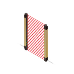

Safety Light Curtain SF4B-H32 SF4B-H32E + SF4B-H32D

Spec Detail
| Item | Specifications |
|---|---|
| Product Number | SF4B-H32(V2) |
| Part Number | SF4B-H32(V2) |
| CE marking directive compliance | Machinery Directive, EMC Directive, RoHS Directive |
| No. of beam channels | 32 |
| Protective height | 630 mm 24.803 in(Note:In the case of "When used as safety device for presses in China", the distance between the center of the first beam axis and the center of the last beam axis of the device becomes the protective height. For details, refer to "Definition of sensing heights".) |
| Protective height : China Press compliant (GB/T 4584) | 620mm 24.409 in |
| Current consumption | Emitter: 80 mA or less Receiver: 115 mA or less |
| PFHD | 2.8 × 10⁻⁹ |
| MTTFD | 100 years or more |
| Weight(Total of emitter and receiver) | 1,260 g approx. |
| Applicable standards:International standard | IEC 61496-1/2 (Type 4), ISO 13849-1 (Category 4, PLe), IEC 61508-1 to 7 (SIL3) (Note) PLe SIL3 compliant from production in August 2009. |
| Applicable standards:Japan | JIS B 9704-1/2 (Type 4), JIS B 9705-1 (Category 4), JIS C 0508-1 to 7 (SIL3) (Note) PLe SIL3 compliant from production in August 2009. |
| Applicable standards:Europe (EU) | EN 61496-1 (Type 4), EN ISO 13849-1 (Category 4, PLe), EN 61508-1 to 7 (SIL3), EN 55011, EN 50178, EN 61000-6-2 (Note) PLe SIL3 compliant from production in August 2009. |
| Applicable standards:North America | ANSI/UL 61496-1/2 (Type 4), ANSI/UL 508, UL 1998 (Class 2), CAN/CSA 61496-1/2 (Type 4), CAN/CSA C22.2 No.14, OSHA 1910.212, OSHA 1910.217(C), ANSI B11.1 to B11.19, ANSI/RIA 15.06 (Note) PLe SIL3 compliant from production in August 2009. |
| Applicable standards:South Korea (S-Mark) | S1-G-35-2005, S2-W-11-2003 (Note) PLe SIL3 compliant from production in August 2009. |
| Applicable standards:China (GB) | GB/T 4584 (Note) PLe SIL3 compliant from production in August 2009. |
| Operating range | 0.3 to 9 m 0.984 to 29.528 ft (Note) The operating range is the possible setting distance between the emitter and the receiver. |
| Min. sensing object | ø25 mm ø0.984 in opaque object (Note) When the floating blanking function is used, the size of the min. sensing object is changed. |
| Effective aperture angle | plus or minus 2.5°or less [for an operating range exceeding 3 m 9.843 ft(conforming to IEC 61496-2 / ANSI/UL 61496-2)] |
| Power voltage | 24 V DC plus or minus 10 % Ripple P-P 10 % or less |
| Control outputs (OSSD 1, OSSD 2) | PNP open-collector transistor / NPN open-collector transistor (switching method) - When selecting PNP output: Max. source current 200 mA, When selecting NPN output: Max. sink current 200 mA - Applied voltage: same as supply voltage (When selecting PNP output: between the control output and +V, When selecting NPN output: between the control output and 0 V) - Residual voltage: 2.5V or less (When selecting PNP output: source current 200 mA, when selecting NPN output: sink current 200 mA) (when using 20 m 65.617 ftlength cable) |
| Control outputs (OSSD 1, OSSD 2):Operation mode | ON when all beam channels are received, OFF when one or more beam channels are interrupted (OFF also in case of any malfunction in the safety light curtain or the synchronization signal) (Note) The outputs are not ''OFF'' when muting function is active even if the beam channel is interruped. (Note) In case the blanking function is valid, the operation mode is changed. |
| Control outputs(OSSD1, OSSD2):Protection circuit | Incorporated |
| Response time | OFF response: 14 ms or less, ON response: 80 to 90 ms |
| Auxiliary output (Non-safety output) | PNP open-collector transistor / NPN open-collector transistor (switching method) - When selecting PNP output: Max. source current 60 mA, When selecting NPN output: Max. sink current 60 mA - Applied voltage: same as supply voltage (When selecting PNP output: between the auxiliary output and +V, When selecting NPN output: between the auxiliary output and 0 V) - Residual voltage: 2.5V or less (When selecting PNP output: source current 60 mA, when selecting NPN output: sink current 60 mA) (when using 20 m 65.617 ftlength cable) |
| Auxiliary output (Non-safety output):Operation mode | OFF when control outputs are ON, ON when control outputs are OFF (Factory setting; operating mode can be changed using the SFB-HC handy-controller(optional)). |
| Auxiliary output (Non-safety output):Protection circuit | Incorporated |
| Auxiliary output (Non-safety output):Responce time | OFF replay: 34 ms or less, ON replay 110 ms or less |
| Interference prevention function | Incorporated (Note) Please use 12-core cable. |
| Emission halt function | Incorporated |
| Interlock function | Incorporated [Manual reset / Auto reset (Note)] (Note) The manual reset and auto reset are possible to be switched depending on the wiring status. |
| External device monitoring function | Incorporated |
| Override function | Incorporated (Note) Please use 12-core cable. |
| Muting function | Incorporated (Note) Please use 12-core cable. |
| Optional functions | Fixed blanking, floating blanking, auxiliary output switching, interlock setting changing, external relay monitor setting changing, muting setting changing, protecting, light emitting amount control (Note) In case of using optional function, the handy-controller (SFB-HC) (optional) is required. However, a handy-controller cannot be used with the SF4B-x-01<V2> and the SF-C14EX-01. |
| Environmental resistance:Degree of protection | IP67 / IP65 (IEC) |
| Ambient temperature | -10 to +55 °+14 to +131 ℉ (No dew condensation or icing allowed), Storage: -25 to +70 °-13 to +158 ℉ |
| Ambient humidity | 30 to 85 % RH, Storage: 30 to 95 % RH |
| Ambient illuminance | Incandescent light: 3,500 lx or less at the light-receiving face |
| Environmental resistance:Dielectric strength voltage | 1,000 V AC for one min. between all supply terminals connected together and enclosure |
| Insulation resistance | 20 MOhm , or more, with 500 V DC megger between all supply terminals connected together and enclosure |
| Vibration resistance | 10 to 55 Hz frequency, 0.75 mm 0.030 in double amplitude in X, Y and Z directions for two hours each |
| Shock resistance | 300 m/s2 acceleration (30 G approx.) in X, Y and Z directions three times each |
| Emitting element | Infrared LED (Peak emission wavelength: 870 nm 0.034 mil) |
| Material | Enclosure: Aluminium Upper and lower edges: Iron Sensing surface: Polycarbonate / Polyester resin Cap: PBT |
| Connecting method | Connector |
| Cable length | Total length up to 50 m 164.042 ft is possible for both emitter and receiver, with optional mating cables (Note) The cable can be extended within 30 m 98.425 ft (for emitter / receiver) when two light curtains are connected in series, within 20 m 65.617 ft when three light curtains are connected in series. Furthermore, when the muting lamp is used, the cable can be extended within 40 m 131.234 ft (for emitter / receiver). |
